A Comprehensive Guide to Karnaugh Maps and their Application in Digital Logic Design
Related Articles: A Comprehensive Guide to Karnaugh Maps and their Application in Digital Logic Design
Introduction
With enthusiasm, let’s navigate through the intriguing topic related to A Comprehensive Guide to Karnaugh Maps and their Application in Digital Logic Design. Let’s weave interesting information and offer fresh perspectives to the readers.
Table of Content
A Comprehensive Guide to Karnaugh Maps and their Application in Digital Logic Design
Introduction
In the realm of digital logic design, Karnaugh maps, commonly known as K-maps, are a powerful tool for simplifying Boolean expressions. These graphical representations offer a visual approach to minimizing logic circuits, leading to more efficient and cost-effective designs. This article provides a comprehensive exploration of K-maps, delving into their fundamental concepts, applications, and practical benefits in the field of digital logic design.
Understanding Karnaugh Maps
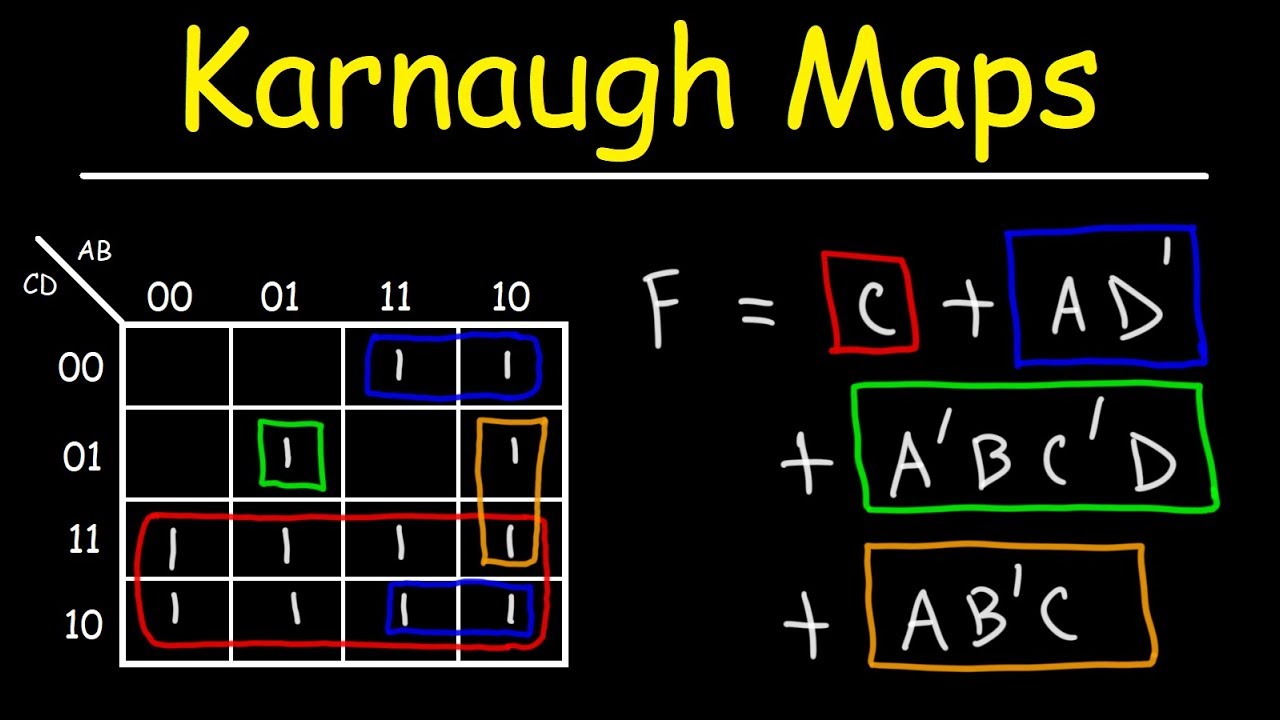
A Karnaugh map is a visual representation of a truth table, a tabular method for displaying the output of a logic function for all possible combinations of its input variables. Each cell in the K-map corresponds to a unique combination of input values, and the cell’s content represents the corresponding output value (either 0 or 1).
Key Features and Construction
- Grid Structure: K-maps are typically constructed as a grid, with rows and columns representing the different combinations of input variables. The number of rows and columns depends on the number of input variables.
- Gray Code Ordering: The order of the rows and columns is determined by the Gray code, a binary code where only one bit changes between successive entries. This ensures that adjacent cells in the K-map represent input combinations that differ by only one bit.
- Adjacent Cells: Adjacent cells in a K-map represent input combinations that differ by a single bit. This adjacency is crucial for identifying groups of 1s, which represent minterms or maxterms.
Simplifying Boolean Expressions with K-Maps
The primary function of K-maps is to simplify Boolean expressions. This simplification is achieved by grouping adjacent cells containing 1s. Each group represents a product term (AND operation) in the simplified expression.
Steps for Simplifying Boolean Expressions using K-Maps:
- Construct the K-Map: Create a K-map with the appropriate number of rows and columns based on the number of input variables.
- Fill the K-Map: Enter the output values (0 or 1) from the truth table into the corresponding cells of the K-map.
- Identify Groups of 1s: Circle groups of adjacent 1s, ensuring that the groups are as large as possible. A group can include cells on the edges or even wrap around the map.
- Write the Simplified Expression: For each group, write down the product term corresponding to the input variables that are common to all cells in the group.
- Combine the Product Terms: Combine the product terms with OR operations to form the final simplified Boolean expression.
Advantages of Using K-Maps
- Visual Approach: K-maps provide a visual representation of the Boolean expression, making it easier to identify patterns and simplify the logic.
- Simplified Expressions: K-maps offer a systematic way to derive simplified expressions, reducing the number of logic gates needed to implement the function.
- Reduced Circuit Complexity: Simplifying the Boolean expression directly translates to a reduction in the number of logic gates required, resulting in a smaller, less complex, and more efficient circuit.
- Improved Circuit Performance: Reduced complexity leads to lower propagation delays and improved circuit performance.
- Cost-Effectiveness: Fewer logic gates translate to lower component costs and reduced power consumption.
Applications of Karnaugh Maps
K-maps find extensive applications in various fields of digital logic design, including:
- Logic Circuit Design: Simplifying Boolean expressions for logic gates, leading to optimized and efficient circuits.
- Combinational Circuit Design: Designing combinational circuits like adders, subtractors, decoders, and encoders.
- Sequential Circuit Design: Simplifying state transition logic in sequential circuits like flip-flops and counters.
- Digital System Design: Optimizing logic functions for digital systems like microprocessors, memory controllers, and communication systems.
Practical Examples of K-Map Applications
-
Designing a 2-Input AND Gate:
-
The truth table for a 2-input AND gate is:
Input A Input B Output 0 0 0 0 1 0 1 0 0 1 1 1 -
The corresponding K-map is:
AB 00 01 11 10 0 0 0 1 0 1 0 0 1 0 -
Grouping the single ‘1’ in the K-map, we get the simplified expression: AB.
-
-
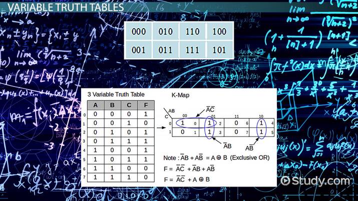
Designing a 3-Input XOR Gate:
-
The truth table for a 3-input XOR gate is:
Input A Input B Input C Output 0 0 0 0 0 0 1 1 0 1 0 1 0 1 1 0 1 0 0 1 1 0 1 0 1 1 0 0 1 1 1 1 -
The corresponding K-map is:
ABC 000 001 011 010 110 111 101 100 0 0 1 0 1 1 0 0 1 1 0 1 0 0 1 0 -
Grouping the four ‘1’s in the K-map, we get the simplified expression: A’BC’ + AB’C’ + ABC + A’B’C.
-
FAQs
Q1: What is the maximum number of input variables that can be represented in a K-map?
A1: The number of input variables that can be represented in a K-map depends on the size of the grid. For a standard 2×2 K-map, the maximum is 2. For a 4×4 K-map, it’s 4. In general, for a 2^n x 2^n K-map, the maximum number of input variables is n.
Q2: Can K-maps be used for functions with more than four input variables?
A2: While standard K-maps are limited to four input variables, there are methods for handling functions with more inputs. One approach is to use multiple K-maps, where each map represents a subset of the input variables. Another method involves using alternative graphical representations like the Quine-McCluskey method.
Q3: How do I handle "don’t care" conditions in a K-map?
A3: "Don’t care" conditions occur when the output value for a specific input combination is irrelevant. These conditions can be marked as "X" in the K-map. During grouping, "don’t cares" can be included with 1s to form larger groups, further simplifying the expression.
Q4: What are the limitations of K-maps?
A4: K-maps are primarily suited for simplifying Boolean expressions with a limited number of input variables. For functions with a large number of inputs, alternative methods like the Quine-McCluskey algorithm might be more efficient.
Tips for Using K-Maps Effectively
- Start with a Truth Table: Always begin by constructing a truth table for the logic function you want to simplify.
- Understand Gray Code Ordering: Familiarize yourself with the Gray code ordering to ensure accurate placement of input combinations in the K-map.
- Maximize Group Size: Aim to form groups of 1s that are as large as possible. Larger groups lead to simpler product terms.
- Don’t Forget Wrap-Around: Groups can wrap around the edges of the K-map. Don’t overlook these potential groupings.
- Use "Don’t Cares" Wisely: Utilize "don’t cares" strategically to maximize group size and simplify the expression.
Conclusion
Karnaugh maps are a valuable tool for simplifying Boolean expressions and optimizing digital logic circuits. Their visual approach, systematic grouping techniques, and ability to handle "don’t care" conditions make them an indispensable resource for digital logic designers. By mastering the art of K-map simplification, engineers can achieve more efficient, cost-effective, and reliable digital systems.


Closure
Thus, we hope this article has provided valuable insights into A Comprehensive Guide to Karnaugh Maps and their Application in Digital Logic Design. We thank you for taking the time to read this article. See you in our next article!