Unveiling the Power of Karnaugh Maps: A Comprehensive Guide to Simplifying Logic Circuits
Related Articles: Unveiling the Power of Karnaugh Maps: A Comprehensive Guide to Simplifying Logic Circuits
Introduction
In this auspicious occasion, we are delighted to delve into the intriguing topic related to Unveiling the Power of Karnaugh Maps: A Comprehensive Guide to Simplifying Logic Circuits. Let’s weave interesting information and offer fresh perspectives to the readers.
Table of Content
Unveiling the Power of Karnaugh Maps: A Comprehensive Guide to Simplifying Logic Circuits
In the realm of digital electronics, logic circuits form the backbone of complex systems. These circuits, built from fundamental logic gates like AND, OR, NOT, XOR, etc., perform specific operations based on input signals. However, designing and implementing these circuits can be a daunting task, especially when dealing with numerous inputs and complex Boolean expressions. This is where Karnaugh Maps (K-maps) emerge as a powerful tool, simplifying the process of circuit design and optimization.
Understanding the Essence of Karnaugh Maps
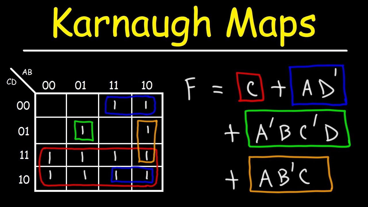
A Karnaugh Map (K-map) is a graphical representation of a truth table, a tabular listing of all possible input combinations and their corresponding output values. K-maps offer a visual and intuitive approach to simplifying Boolean expressions, ultimately leading to more efficient and cost-effective circuit implementations.
The Key Principles of K-Maps
The core principle behind K-maps lies in grouping adjacent cells representing "minterms" (product terms) in the truth table. These groups, known as "implicants," represent simplified Boolean expressions that capture the same logic as the original expression. The simplification process relies on the following key concepts:
-
Adjacency: Cells in a K-map are considered adjacent if they differ in only one input variable. This adjacency is crucial for grouping cells and deriving simplified expressions.
-
Grouping: The goal is to group adjacent cells containing "1"s (representing true outputs) into the largest possible groups, forming implicants. These groups should be rectangular or square, with powers of two (1, 2, 4, 8, etc.) in their area.
-
Essential Prime Implicants: Some groups are essential because they cover minterms that cannot be covered by any other group. These are called "essential prime implicants" and must be included in the final simplified expression.
-
Non-Essential Prime Implicants: Other groups may cover minterms that can also be covered by other groups. These are non-essential prime implicants and are included in the final expression based on minimizing the total number of literals (input variables) in the expression.
Construction and Interpretation of K-Maps
K-maps are constructed based on the number of input variables. A 2-variable K-map has four cells, a 3-variable K-map has eight cells, and so on. The cells are arranged in a specific pattern, ensuring that adjacent cells differ in only one input variable.
Each cell in the K-map represents a unique combination of input variables, and the value within the cell represents the corresponding output value (0 or 1) from the truth table.
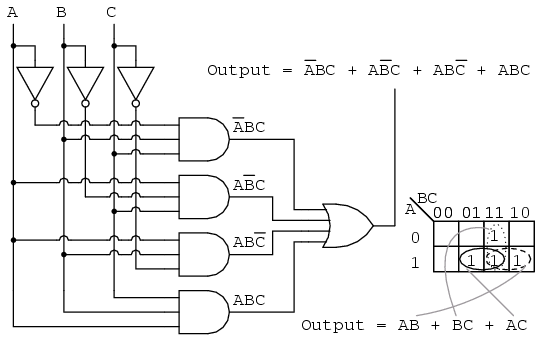
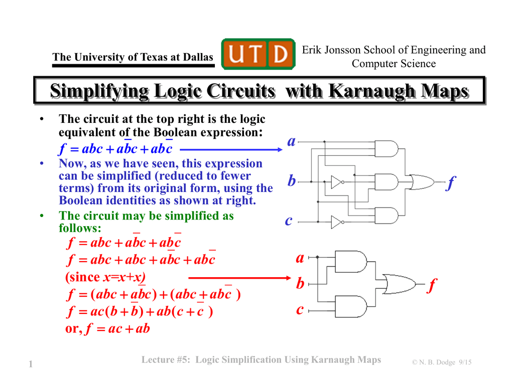
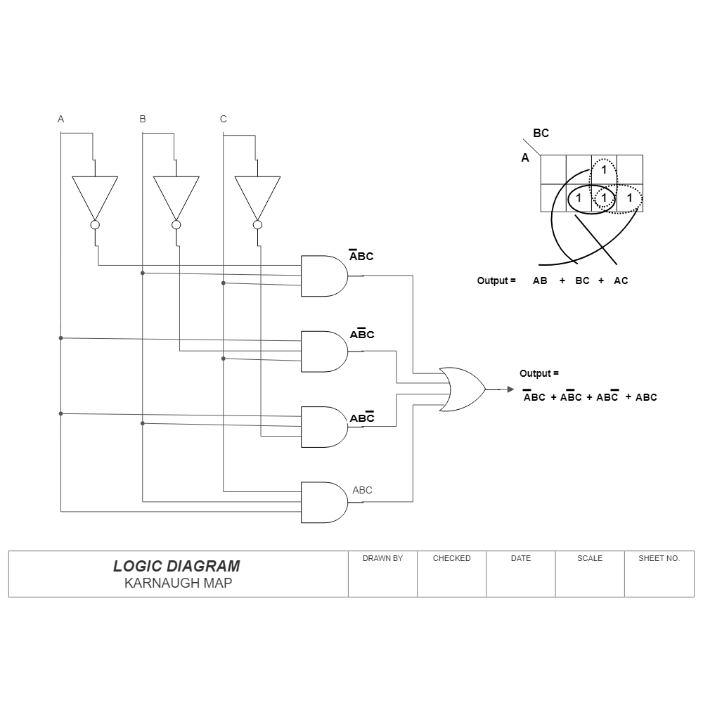
Illustrative Example: Simplifying a Boolean Expression
Consider the following Boolean expression:
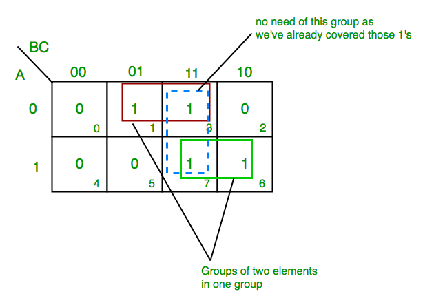
F(A, B, C) = Σ(0, 1, 2, 3, 5, 7)This expression represents a function with three input variables (A, B, C) and outputs "1" for the input combinations 0, 1, 2, 3, 5, and 7. To simplify this expression using a K-map, we follow these steps:
-
Construct the K-map: A 3-variable K-map is constructed with eight cells, as shown below:
AB | 00 | 01 | 11 | 10 C | | | | 0 | 1 | 1 | 1 | 1 1 | 1 | 0 | 1 | 0 -
Populate the K-map: The cells corresponding to the minterms (0, 1, 2, 3, 5, 7) are filled with "1"s, while the remaining cells are filled with "0"s.
-
Group the 1s: We identify the largest possible groups of adjacent "1"s. In this example, we have one group of four "1"s covering the minterms 0, 1, 2, and 3, and another group of two "1"s covering minterms 5 and 7.
-
Derive the Simplified Expression: Each group represents a simplified product term. The group of four "1"s corresponds to the term
A', and the group of two "1"s corresponds to the termBC. -
Final Expression: The simplified expression for the given function is:
F(A, B, C) = A' + BC
The Benefits of Using Karnaugh Maps
-
Simplified Circuit Design: K-maps facilitate the derivation of simplified Boolean expressions, leading to reduced gate count and complexity in the final circuit implementation.
-
Cost-Effectiveness: Reduced gate count translates to lower component cost, smaller circuit board area, and lower power consumption, making the design more cost-effective.
-
Improved Performance: Simpler circuits generally exhibit faster switching speeds and improved noise immunity, leading to better overall performance.
-
Ease of Implementation: K-maps provide a visual and intuitive approach to logic simplification, making the process easier for designers to understand and implement.
Addressing Common Questions about Karnaugh Maps
Q1: What is the maximum number of variables that can be handled by a K-map?
A: While K-maps can be used for up to six variables, their effectiveness diminishes beyond four variables due to the increasing complexity of the map. For more complex circuits, other methods like Quine-McCluskey minimization are preferred.
Q2: How to handle "don’t care" conditions in a K-map?
A: "Don’t care" conditions represent input combinations where the output is irrelevant. These conditions can be represented by an "X" in the K-map. During grouping, "X"s can be treated as "1"s to form larger groups, further simplifying the expression.
Q3: Can K-maps be used for multi-output circuits?
A: Yes, K-maps can be used for multi-output circuits. Each output function is represented by a separate K-map, and the simplification process is applied independently to each map.
Q4: Are there any limitations to using K-maps?
A: K-maps are primarily suitable for circuits with a limited number of input variables. For more complex circuits, other minimization techniques like Quine-McCluskey may be more efficient.
Tips for Efficient K-Map Usage
-
Start with a clear truth table: Ensure that the truth table is accurate and complete before constructing the K-map.
-
Choose the appropriate K-map size: Select a K-map with the correct number of cells based on the number of input variables.
-
Utilize the adjacency property: Carefully identify and group adjacent cells containing "1"s to form the largest possible groups.
-
Identify essential prime implicants: Ensure that all essential prime implicants are included in the final simplified expression.
-
Minimize the number of literals: Choose non-essential prime implicants strategically to minimize the total number of literals in the final expression.
Conclusion: Embracing the Power of Karnaugh Maps
Karnaugh Maps provide a powerful and efficient method for simplifying Boolean expressions and optimizing logic circuits. They offer a visual and intuitive approach to logic minimization, leading to simpler, more cost-effective, and higher-performing circuit designs. Understanding the principles of K-maps is essential for any electronics engineer or student seeking to design and implement efficient digital circuits. By mastering this technique, designers can unlock the full potential of logic circuits, paving the way for innovative and sophisticated electronic systems.


Closure
Thus, we hope this article has provided valuable insights into Unveiling the Power of Karnaugh Maps: A Comprehensive Guide to Simplifying Logic Circuits. We hope you find this article informative and beneficial. See you in our next article!